ELECTRONICS
Circuitry, Schematics, Wiring
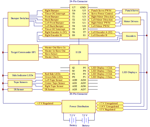
Block Diagram
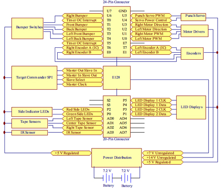
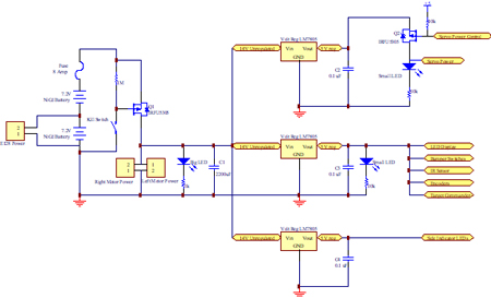
Power Distribution
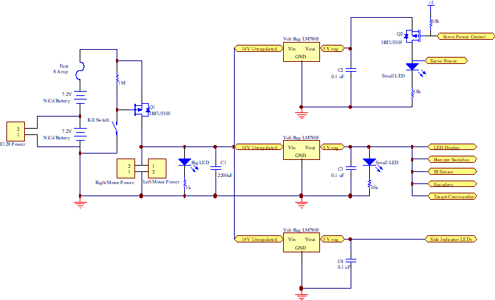
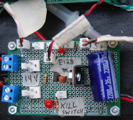
Our power distribution system used two 7.2V NiCd batteries to provide 14.4 V to our motors and with three LM7805 5V 1Amp voltage regulators to distribute logic level voltage to our circuits. The motors were powered straight from the 14.4 V of the batteries, while the E128 board, having its own voltage regulator, was powered from one of the batteries. To prevent damage from accidentally plugging the batteries in backwards we included a P-channel power MOSFET (the IRF5305 capable of sourcing over 20Amps) which would only open when the batteries were corrected in the proper polarity.
We also used this transistor to implement a kill switch to quickly power off the robot if it was necessary. An 8amp fuse was used to protect our circuitry in the case of a short. 3 voltage regulators were used. One provided power for the side indicator LED’s which drew on the order of 50mA. A second regulator was supplied to provide power to the servo motor which could draw currents up to 450mA. The rest of our circuits obtained power from a third 5V regulator. Since we weren’t using the tape sensors nor the IR beacon detector, this regulator only has to supply power to our LED display which drew ~100 mA, while the encoders and switches drew very little current. Small power indicator LEDs were used to signal that power was reaching the various circuits.
A large 2200uF bypass cap was placed on the unregulated 14.4V side of the power board to reduce noise on the supply line due to the large current drawn by the motors. As per datasheet recommendations a 0.1 uF was placed on the regulated side of the regulators, to smooth voltage ripple from the regulators.
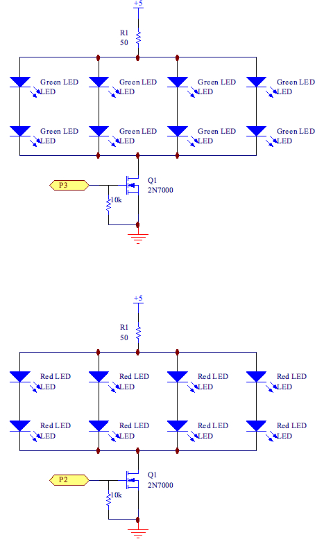
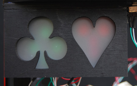
Side Indicator LEDsIn order to indicate which side of the board we were playing on, red or green, we decided to use red and green LEDs on the sides of Alice.
Although not good engineering practice, we chose to place the LEDs in parallel for easy on/off control using a 2N7000 mosfet. Each LED had a forward voltage of about 2V, thus whenever the transistor was in its open state, the current flowing through the 50 ohm resistor was 20mA. Subsequently each diode had about 5mA flowing through them. Although we used this parallel setup, the lights still shone with even brightness. The 2N7000 has a maximum continuous drain current of 200mA, well above the 20mA that we were flowing through the system. A pull down resistor with a value of 10K was used to ensure the gate of the mosfet was adequately pulled down.
2N7000 and the E128
2N7000 requires 3.5V min to turn on; E128 Voh is Vdd – 0.8 = 4.2V (adequate)
2N7000 requires 0.8V max to turn off; E128 Vol is 0.8 max (adequate)
2N7000 requires 10nA max for Iih; E128 Ioh = up to + 10mA (adequate)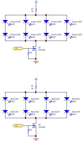
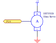
Punch Servo MotorIn our servo selection we decided to choose a bulkier servo that would be capable of easily lifting our puncher setup numerous times in a robust manner. The HS755HB servo made by Hitec was perfectly suited for our needs. At idle the current drawn by the servo was 8mA. When running, the current could reach a max of 450mA, with a typical current of 230mA. A separate regulator was setup with its sole purpose to supply power to the servo. Hitecs datasheets did not list Vih and Vil requirements, but after thorough testing it was found that the E128 provided perfect control over the servo control line.
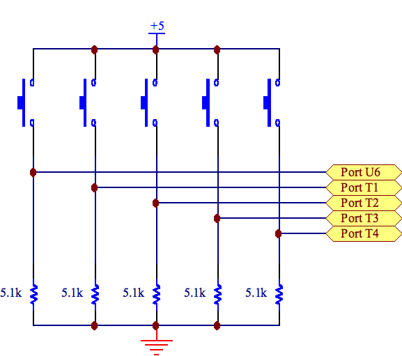
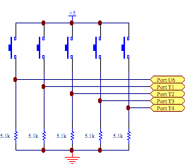
Bumper SwitchesThe bumper circuit was set up quite simply with pull down resistors. When the switch was engaged it would close a circuit that would take the input of the E128 up to 5V, and when not engaged the input of the E128 would be held at ground. Whenever a switch was engaged, 0.98 mA of current would flow through that line. Thus the power dissipated (4.9 mW) was very small. Furthermore, this setup was chosen to save on power drawn from the battery as the bumpers were rarely engaged.
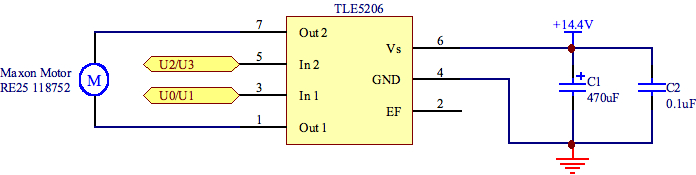
Motor Driver (H-bridges)We used TLE5206 integrated H-bridge circuits to drive our motors. These chips provide a full H-bridge capable of sourcing a continuous 5amps. The rise time of a PWM signal in the chip is slow and therefore we needed to calculate what kind of error we were getting in our output PWM. We calculated that at a PWM frequency of 100Hz, there would be a 2% error in the high time of a 10% duty cycle signal. The higher the frequency of the PWM the more error is caused by this slow rise time. However, since we were going to use PID control of our system the actual output PWM shape from the TLE5205 was not important. The controller would simply adjust the input PWM signal until the desired output was where it needed to be. This way we could run our motors at a higher frequency of 10kHz, where the behaved better.
TLE5206 and the E128
TLE5206 requires at least 6V to run; 14.4V batteries - Vfh (1.5V) - Vfl(1.5V) (adequate)
TLE5206 Iih / Iil is -2uA / 10uA; E128 provides up to 10mA (adequate)
TLE5206 Vih / Vil is 2.8V / 1.2V; E128 Voh / Vol is 4.2V / 0.8V (adequate)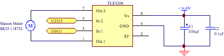
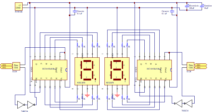
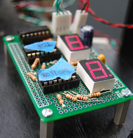
LED DisplaySince our robot was to function autonomously and not connected to the computer terminal we thought it would be a good idea to have LED displays which would give us information about the state of our robot. We used these to mainly to display the target that was being transmitted through the target commander and the target that our robot was heading for. These LED displays also functioned to indicate internal errors, which helped in our debugging.
Each 7-segment LED display (NTE3079) was controlled by a HC164 shift register in order to shift the proper segment sequence into the display. Since the E128 protection board degraded the rise time of the its output signals, a double hex inverter (74HC14) was used to sharpen up the rising edges of the shift register's clock. With a forward voltage drop for a segment of 2V we chose 1k resistors to limit the current to each segment at 3mA. The HC164s can source up to 25mA per channel.
The HC164 and the E128:
HC164 has Vih / Vil of 3.15V / 0.9V; E128 has Voh / Vol of 4.2V / 0.8V (adequate)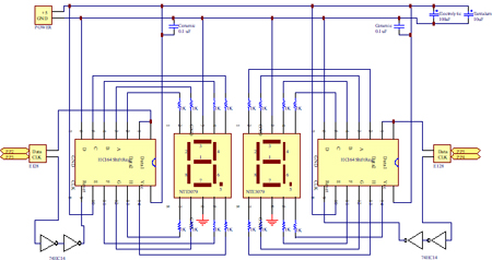
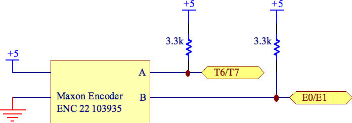
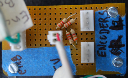
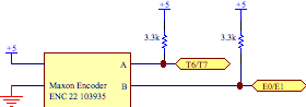
EncodersThe supply voltage for the encoders was 5V, and stated to have a TTL compatible output signal with the above pull-up resistor setup in the data sheet. The signal rise and fall times (200ns, and 50ns) were substantially smaller than the length of our observed periods for the wheels turning. The output current per each channel was a min of -1mA and a max of 5mA, which made it perfectly adequate for use with the E128 which only requires +/- 0.25 uA.
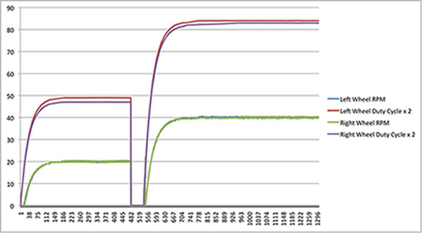
PID TuningBelow one can find a graphical representation of our motor control. The y-axis consists of both motor RPM and two times the duty cycle being provided to the Maxon motors. The x-axis is a representation of time, measured in 20ms per data point. Proportional and integral closed loop control was used so that we could achieve a steady RPM for both wheels by pulsing the Maxon motors with varying duty cycles. The response time was purposely chosen to be slower so that the motor would naturally ramp up, allowing the back EMF to increase. This allowed us to place a higher voltage across the motor once it was moving to achieve even greater speeds without overwhelming our h-bridge with too much current. A proportional gain of 0.1 and an integral gain of 0.05 was used. Furthermore, integrator anti-windup was included in the control algorithm to avoid any overshoot. The result, as can be seen above, is a relatively steady motor RPM (limited by both how refined we could make the duty cycle and how precisely we could measure instantaneous RPM) that ramps up relatively slowly and allowed for precise control over both wheels.
Target CommanderRadio communications between the robot and the game board was mediated using a "Target Commander" which connected to the E128 board through its SPI bus. We chose to run the SPI at its lowest baud rate since speed of data transfer was not an issue.
The Target Commander (TC) and the E128 SPI bus:
TC has Vih / Vil of 3.25V / 1.75V; E128 has Voh / Vol of 4.2V / 0.8V (adequate)
TC has Voh / Vol of 4.6V / 0.4V; E128 has Vih / Vil of 2V / 0.8V (adequate)
TC has Iih / Iil of 1uA; E128 Ioh / Iol up to +/- 10mA (adequate)
TC has Ioh /Iol of +/- 20uA; E128 requries +/- 1 uA (adequate)
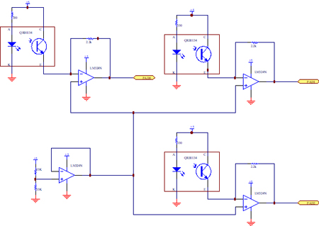
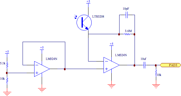
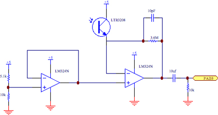
IR Detection (not used in final version of Alice)For the phototransistor circuit we set the corner frequency of the high pass filter to be 1 / (2πRC) = 1 / (2π * 0.10µF * 10kΩ) = 106.1 Hz which is far less than our signal of interest (1250 Hz). In the trans-resistive part of the beacon sensing circuit we added a 10 pF capacitor in parallel with the 3.6MΩ feedback resistor to filter out any high frequency noise. The first opamp is used as a buffering system from the voltage divider of 5K and 10K. Correspondingly the phototransistor is biased at a Vbe of 3V, and the gain was determined for long range use, although we acknowledge that at closer ranges the opamp does reach saturation and therefore may have a slower response time. See the tape sensor circuit for LM324N and E128 interface voltages and currents.
Note: All thresholds for the IR sensors were located in software, in particular defs.h
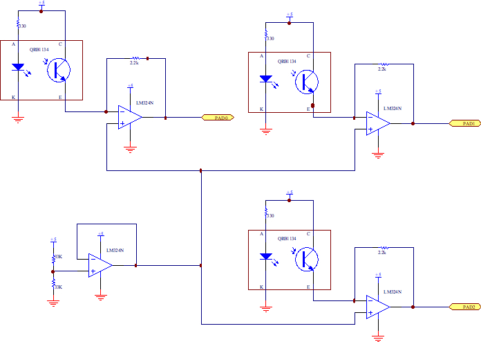
Tape Sensors (not used in final version of Alice)Three separate tape sensor systems were set up for our use. One opamp was used as a buffer at V+ for each of the three amplification systems that we set up to detect a signal. A resistor of 2.2K was chosen through trial and error so that the gain was significant enough differentiate green/red tape from black tape at the various voltages. The emitter was set at a forward voltage of 5V – 3.5V = 1.5V as it had a maximum spec for forward voltage of 1.7V. At this level we could expect a current flow of greater than 10mA to be generated when in the presence of a reflecting object, and on the scale of 100 nA when not sensing (dark current).
LM324N and the E128
E128 requires 3.25V min for Vih; LM324 Voh min: 3.5V (adequate)
E128 requires 1.75V max for Vil; LM324 Vol max: 20 mV (adequate)
Requires Iin of +/-.25 uA; LM324 Ioh / Iol is -10mA / 20mA (adequate)Note: All thresholds for the tape sensors were located in software, in particular defs.h