PROTOTYPES
Iterations on the punching arm...
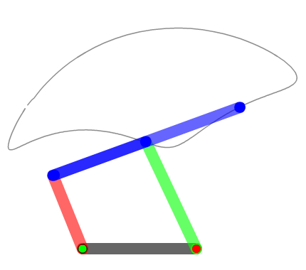
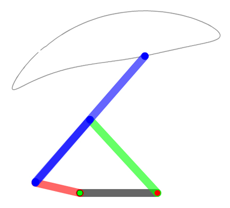
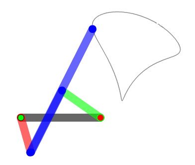
Four-Bar LinkageWe began our punching arm prototypes by exploring linkages. We modeled various sweeps to see how collapsed of an arm we could have while also maximizing the reach and minimizing the angle of the sweep.
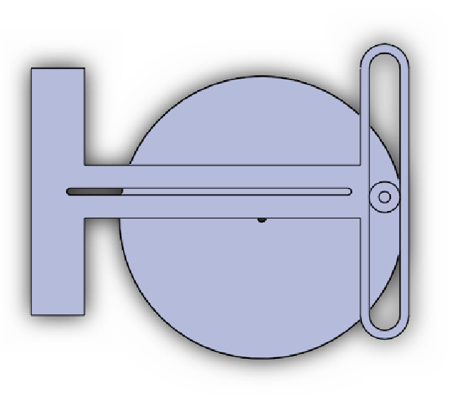
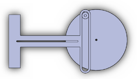
One-Sided CamWe initially designed a one-sided cam mechansim for our puncher. It had a rotating disk with a nubbin that held a rollerblade bearing at the edge of the disk. The center of the disk was linked to the motor so that as the motor rotated, the bearing rotated around the center. The arm of the puncher had a slot that fit around the bearing and allowed the arm to punch straight in and out. After printing these parts on the lasercamm machine we realized that the system was under-constrained -- the puncher did not stay on the disk.
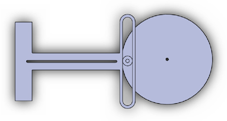
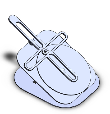
Two-Sided CamIn our second iteration, we decided to use a two-sided cam, in which the arm was constrained on both sides. While this system was more well-constrained, it did not fit as easily within the 12x12 space limit.
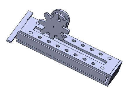
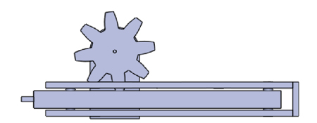
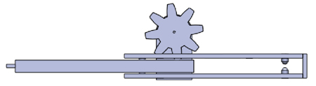
Rack and PinionOne final prototype we built involved a rack and pinion. We iterated several times on the hole spacing in the rack in order to optimize the smooth meshing between the rack and pinion. Then we iterated on the timing in order to ensure that the arm punched out quickly and smoothly (without over-extending).