ELECTRONICS
Circuitry, Schematics, Wiring
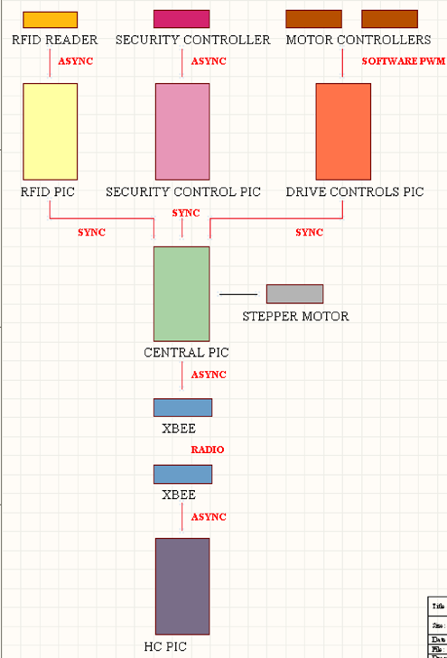
Block Diagram
Front Compartment of Electronics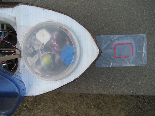
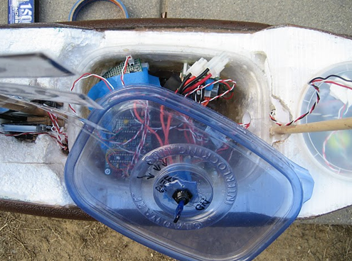
Middle Compartment of Electronics
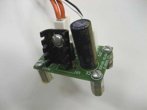
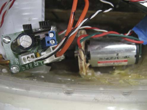
Power Distribution
Our power distribution system on the DCH (boat) uses two 7.2V NiCd batteries in parallel to provide 7.2 V, thereby offering higher current capacity, to our two drive motors. We use a 3Amp switching regulator to distribute logic level voltage to our circuits. The motors are powered straight from the 7.2 V of the batteries, while the xbee boards are designed to have a 3.3 voltage regulator (for the xbee to run on) and a level shifter to run all of our PICs at 5V.
The project specification required a continous HC operation of at least 8 hours. The HC (controller) uses one 7.2V NiCd battery, which is adequate for 8 hours of operation. One 7.2V NiCd battery is rated at 1500 mA-hr. We measured the current through the battery’s leads and read an average of 74.5mA. This gives us a theoretical operating time of
1500 mA-hr / 74.5mA = 20 hours which is well above the 8 hour requirement of the specification.
We also installed a kill switch to quickly power off the boat motors if necessary. As per datasheet recommendations a 0.1 uF is loacated on the regulated side of the regulators, to smooth voltage ripple from the regulators.
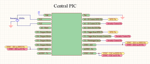
Central PIC
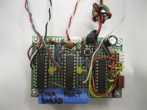
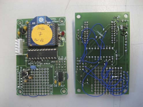
The Central PIC assimilates data (synchronously) from both the RIFD PIC and the Security Control PIC and then communicates asynchronously with the xbee radio system. Because it is communicating synchronously with both the RFID and the security PICs, it has two lines each, connected to the three synchronous ports (SDI, SDO, and SCK)
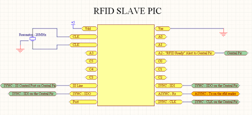
RFID PIC
The RFID PIC communicates asynchronously with the RFID reader. It stores the RFID ascii characters in a 14-character array and then converts it into a hex array of 8 units in length (start character - RFID#1 - RFID#2 - RFID#3 - RFID#4 - RFID#5 - Checksum - end character). As soon as this hex array is assimilated, the RFID PIC sets the A2 port high, sending an alert to the Central PIC which lets the Central PIC know that it should initiate synchronous communication with the RFID PIC as the slave in order to get the RFID data. The SDI line from the RFID PIC was tied to the SDO line of the Central PIC and vice versa, as were the clocks.
(calculations)
Refer to Image in the Security Control Section for the PIC Image.
As soon as the Central PIC has received all the hex data from the RFID PIC, it initializes synchronous communication with the security control PIC in order to pass the RFID data to the security control PIC. Then, the security control PIC communicates with the security controller asynchronously in order to receive the security code information. As soon as the security control PIC has all of the Security Code data, it sets Port C2 high, thereby alerting the Central PIC that the data is ready. Then the Central PIC initiates synchronous communication with the Security Control PIC in order to get all the security data onto the Central PIC.
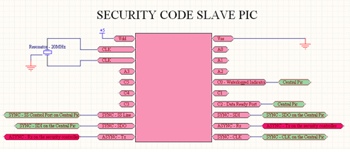
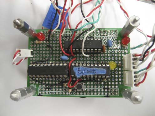
Security PIC is bottom left. Security Controller is bottom right. RFID PIC is upper right.
Drive Motors
There are two Maxon A-max UO3027A motors (one on the starboard and one on the port side of the DCH. We tried to upgrade these motors, but were drawing too much current for the switching regulator and therefore decided to stick with the UO3027A's. We used the h-bridge circuits that we used last quarter for the nice Maxon motors. These TLE5206 integrated H-bridge circuits provide a full H-bridge capable of sourcing a continuous 5amps.
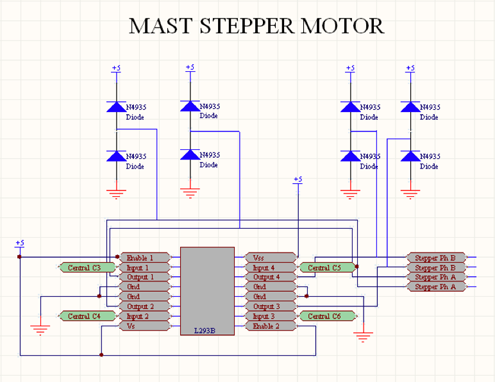
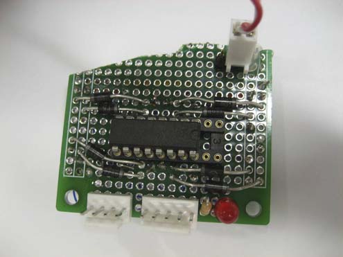
Stepper Motor PIC
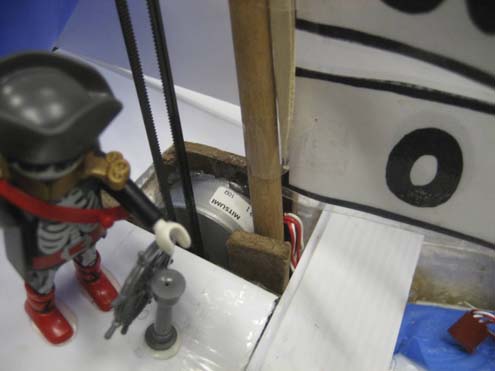
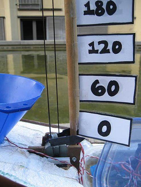
The mast on the DCH (boat) indicates the number of crabs on board at any given point in time (on a scale of 0 to 300 crabs). It is run with an L293B full h-bridge configuration in full step mode, with 8 protection diodes. The mast stepper motor has an internal resistance of 10 ohms, which means that at 5V, it draws a maximum of 500mAmps. This is below the 1A/channel limit of the h-bridge.
XBEE
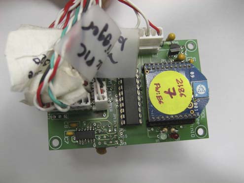
The Central PIC on the boat serves as the master on the boat. It communicates asynchronously with the Xbee radio transmitter and syncronously with each of its slaves: RFID PIC, Security PIC, and Motor PICs. The Xbee transmitter is powered at 3.3 V while the Central PIC (along with all other PICs) is powered at 5 V. This is done with the use of a level shifter and voltage regulator on the Xbee board. The HC PIC has an identical Xbee set up . Both run at a baud rate of 9600 Hz. After attaching motors, we put a resistor across the RX line and ground to minimize noise.
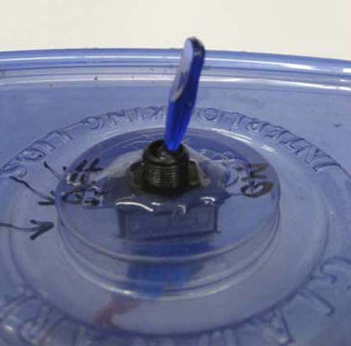
Water Logging
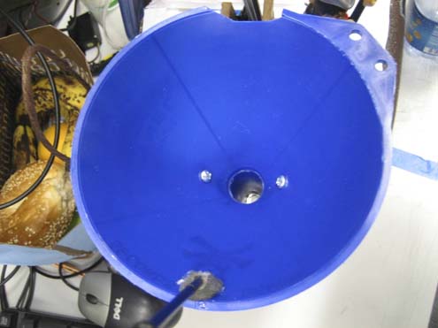
The waterlog sensor is triggered by a small (~100 ohm) resistor, or by water passing through the blue funnel (see image below). When pins 18 and 19 on the security controller are shorted by the water, then pin 2 goes high. This output pin is connected to a Central PIC input.
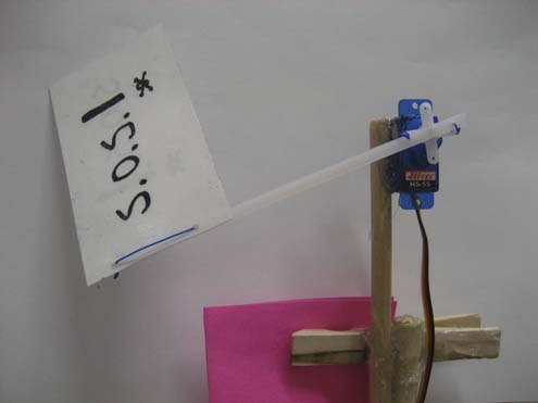
SOS Flag
The SOS flag is triggered whenever there is a water-logging event. This motor is run by software PWM from the motor controller PICs.