| |
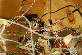 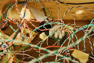 |
| An Ode to Wires |
| Wire, Wire, Wire. Where do you go? |
| Wire, Wire, Wire. Where do you go? |
| Wire, Wire, Wire. Where do you go? |
| I wish you were labeled. |
| |
|
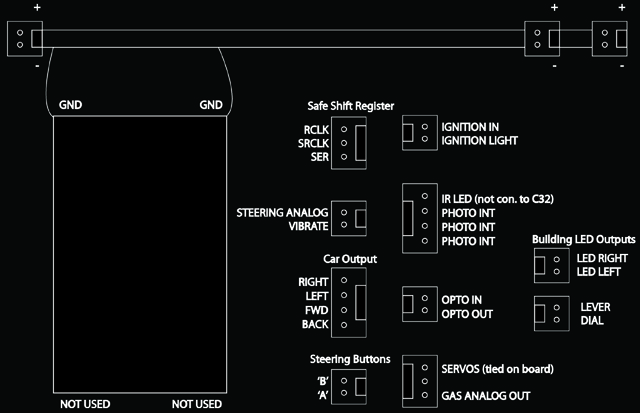
| C32 Pin |
C32 Description |
C32 Pinout |
Notes |
1 |
No Connect |
NONE |
|
|
2 |
Port E0 |
Safe Open Lever |
Digital Input |
|
3 |
Port E1 |
Safe Dial |
Digital Input |
|
4 |
Port T7 |
Safe Shift Register RCLK |
Digital Input |
|
5 |
Port T6 |
Safe Shift Register SRCLK |
Digital Input |
|
6 |
Port T5 |
Safe Shift Register SER |
Digital Input |
|
7 |
Port T4 |
Ignition Switch |
Digital Input |
|
8 |
Port T3 |
Blinking Ignition Light |
Digital Output |
|
9 |
Port T2 |
Fuel Gauge |
Digital Output PWM |
|
10 |
Port T1 |
Car Rev |
Digital Output PWM |
|
11 |
Port T0 |
Car Fwd |
Digital Output PWM |
|
12 |
Port M0 |
Opto Input |
Digital Input |
|
13 |
Port M1 |
Opto Output |
Digital Output |
|
14 |
Ground |
GND |
|
|
15 |
Ground |
GND |
|
|
16 |
Port M2 |
Car Fwd Switch |
Digital Input |
|
17 |
Port M3 |
Car Back Switch |
Digital Input |
|
18 |
Port M4 |
Car Steering Right |
Digital Output |
|
19 |
Port M5 |
Car Steering Left |
Digital Output |
|
20 |
Port AD7 |
Driving Scene Servos |
Digital Output |
|
21 |
Port AD6 |
LED Left Building |
Digital Output |
|
22 |
Port AD5 |
LED Right Building |
Digital Output |
|
23 |
Port AD4 |
Steering Vibrate |
Digital Output |
|
24 |
Port AD3 |
Steering Position Potentiometer |
Analog Input |
|
25 |
Port AD2 |
Safe photo interrupt |
Analog Input |
|
26 |
Port AD1 |
Left Photo interrupt |
Analog Input |
|
27 |
Port AD0 |
Right Photo interrupt |
Analog Input |
|
28 |
No Connect |
NONE |
|
|
|
| |
| Legend: |
Driving controls, |
driving scene, |
safe, |
optointerrupt |
|
| |
| |
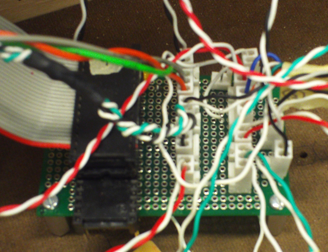
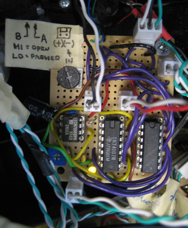
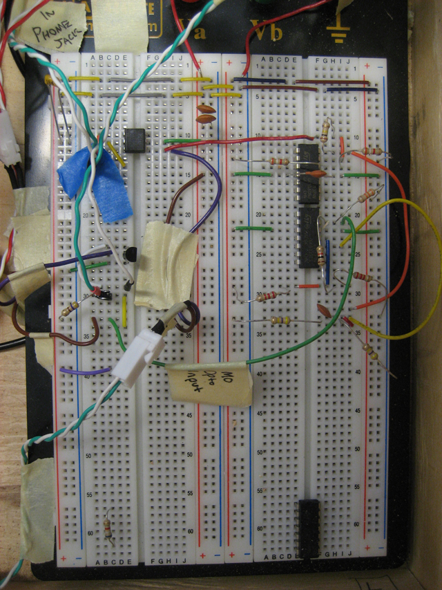
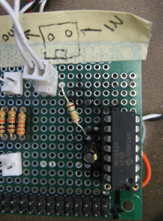
| Our control boards |
| Microcontroller board |
 |
 |
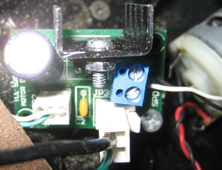
| Power supply board |
  |
| Building control board |
  |
| Servo control board |
 |
 |
| Photo interrupt control board |
 |
 |
| Safe control board |
 |
 |
| Remote control Mini control board |
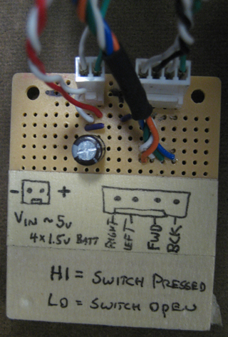  |
| Wheel interface control board |
 |
| |
| |
| Circuit Schematics |
| H11A1 optoisolator input and output |
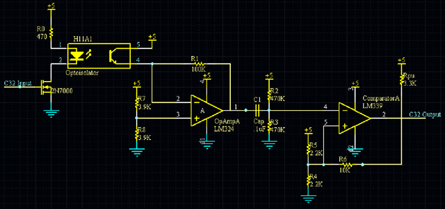 |
| The input on the left side of this circuit controls an LED; turning the LED on via a 2N7000 MOSFET turns the adjacent phototransistor on as well. The signal from the phototransistor goes through a comparator and op-amp to produce a digital output signal. Note that this is extraneous and could be accomplished by reading the analog output signal of the phototransistor with one of the ‘C32’s eight A/D pins. |
 |
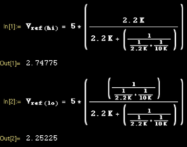
RC filter calculations |
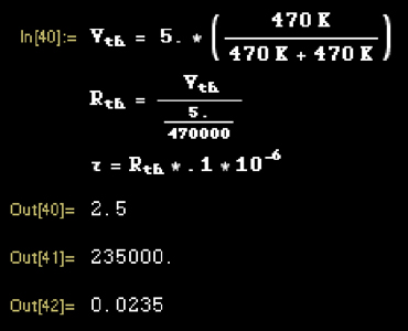 |
Period is 23.5 ms. |
Hysteresis calculations |
 |
| |
Ignition, Safe Dial, Safe Lever (with a limit switch) |
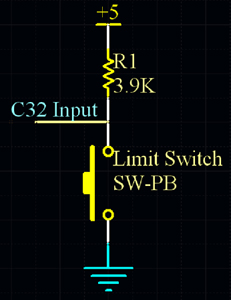 |
| In this circuit, when the switch is open, the input pin of the ‘C32 is pulled up to 5V by the pull-up resistor. When the switch is closed, the voltage at the ‘C32 pin is pulled low to 0V. |
| |
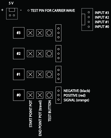
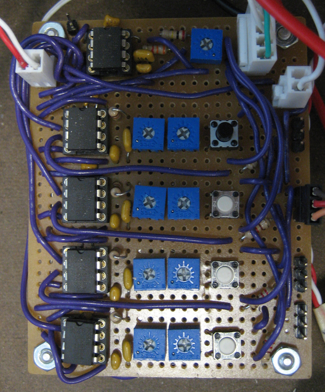
| Gas time display and sign changes (with servo motors) |
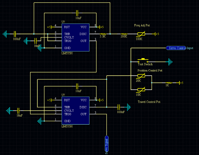 |
| The servo control board is capable of driving four servos based on digital or analog inputs. We decided that it would be easier and less intensive on the microprocessor’s processor to do the servo control with hardware instead of software. A typical RC hobby servo expects a 1-2ms control pulse every 10ms. |
| The board design uses five LM7555 integrated timer chips. The first stage chip is set up in an astable configuration, which outputs a short pulse at about 50 hz, and is adjustable with a trimmer. This carrier wave drives the remaining 4 LM7555 chips which are set up in monostable configurations. When triggered by the carrier wave, the chips output a pulse 1-2 ms in length, controlling the position of the servo. There are two trimmers per second stage LM7555 chip which adjust the starting and ending pulse length when used with a digital signal and adjust offset and gain when using an analog signal input for proportional servo control. |
| In our layout, we used two digital signal from the C32, through the servo control board, to control the servos in the buildings. We used a PWM signal from the C32, through a low pass filter and buffer, through the servo control board, to control the servo used for the gas gauge. |
| |
| Indicator lights: ignition, safe, buildings |
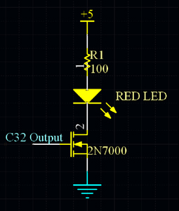 |
| This circuit takes an input from the ‘C32 to control a large LED via a 2N7000 mosfet. |
| |
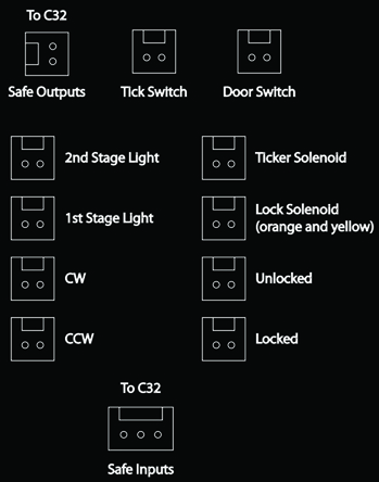
| Safe Lock and Ticker Solenoids |
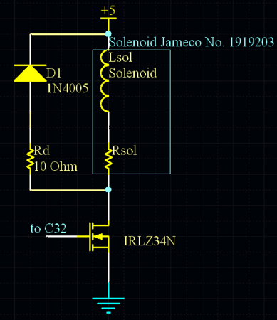 |
Solenoid Calculations: note that solenoid is Jameco #1919203
|
| This circuit powers a small solenoid via a IRLZ34N power mosfet; it contains an additional resistor and diode to protect the mosfet from inductive kickback associated with inductive loads. Since we needed to switch up to 250mA for the solenoid, we chose a power mosfet. We used a high-voltage diode and .5W resistor to prevent damage to the mosfet due to inductive kickback. |
| |
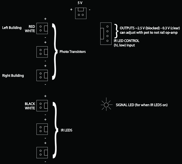
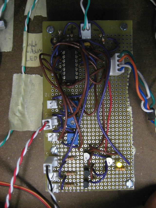
| Safe and Destination photo interrupt sensors |
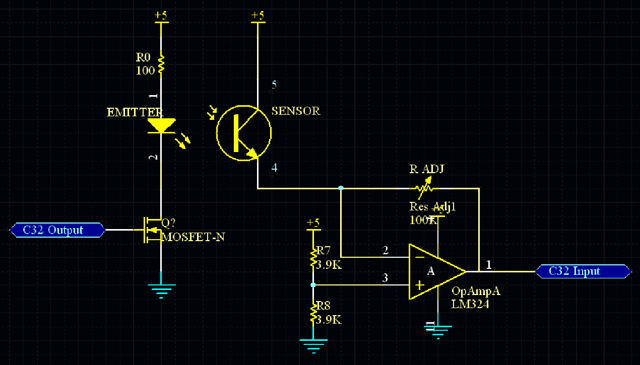 |
| The input on the left side of this circuit controls an IR LED; turning the LED on via a 2N7000 mosfet turns the phototransistor facing the LED on as well. The signal from the phototransistor goes through an op-amp and is sent to the ‘C32. When the path between the LED and the phototransistor is broken, the output goes high to 5V; otherwise, the output is low at 0V. |
| |
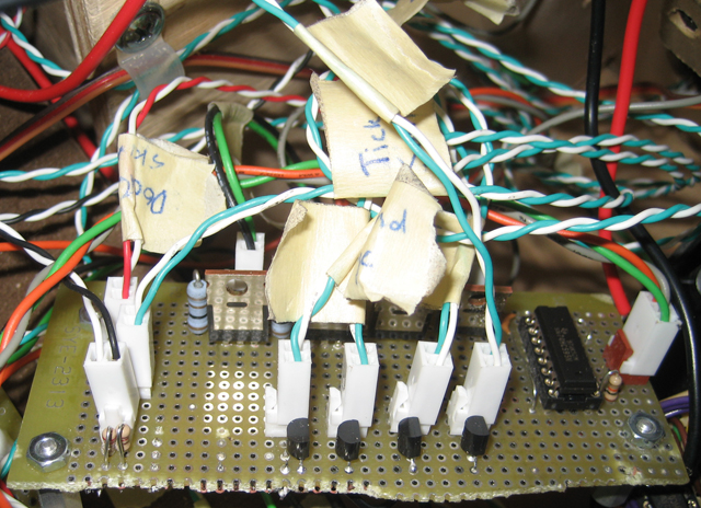
| Shift Register for Safe Outputs |
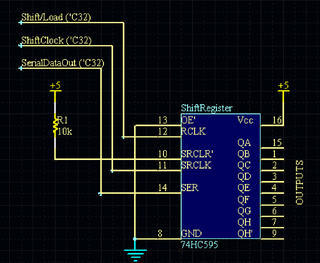 |
| Three outputs from the ‘C32 control the Shift/Load, ShiftClock, and SerialDataOut input pins of the 74HC595 shift register. This expands the output pin capacity of the ‘C32 microcontroller by allowing control of eight output pins at the shift register with only three output pins at the ‘C32. |
| |
| Voltage regulator (5 V) |
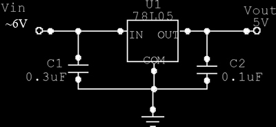 |
| The voltage regulator takes a voltage greater than 5V (in our case 12V) and regulates it down to 5V. In our case, the lamps, solenoids, and other components used in the FLICKER drew more than the allowable 1A of current from the 5V supply of the provided power supply. The 12V supply was capable of providing up to 3A of current, so this supply was used and then regulated down to 5V. |
| |
| Gas gauge |
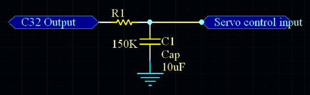 |
| Low pass RC filter that converts a PWM output from the C32 to an analog voltage for the servo control. |
 |
| Wheel Force Feedback Motor H Bridge |
 |
| |
| |
|
| LM78L05 |
| LM339 |
| LM324 |
| LM555 |
| LTR3208 |
| H11A1 |
| Solenoid 12 VDC/.26 A, 45 Ohms 1919203 |
| 74HC595 |
| C32 Pinout |
|
| LTE5208A |
| Heli max servo axe CP |